
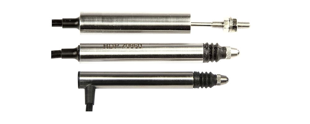
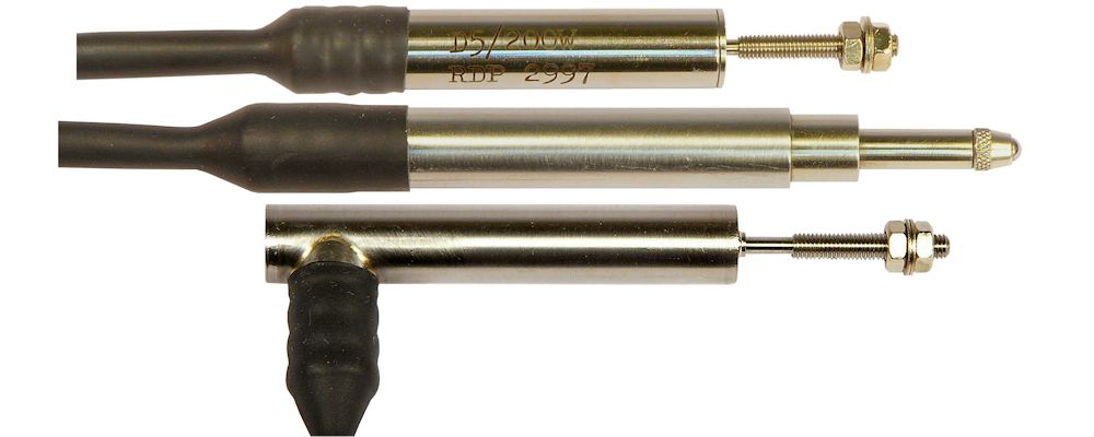
 D5 & D6 LVDT Displacement Transducer
 GT Precision LVDT Gauging Transducer
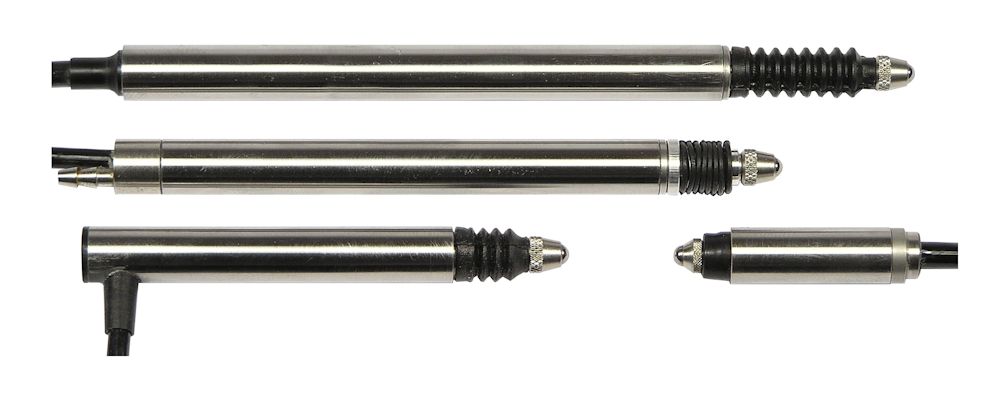
 ACT LVDT Displacement Transducer
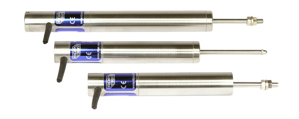
 DCV Series Isolated 0 to 10V Output Displacement Transducer
 DCC Series 4-20mA 2-wire Output Displacement Transducer
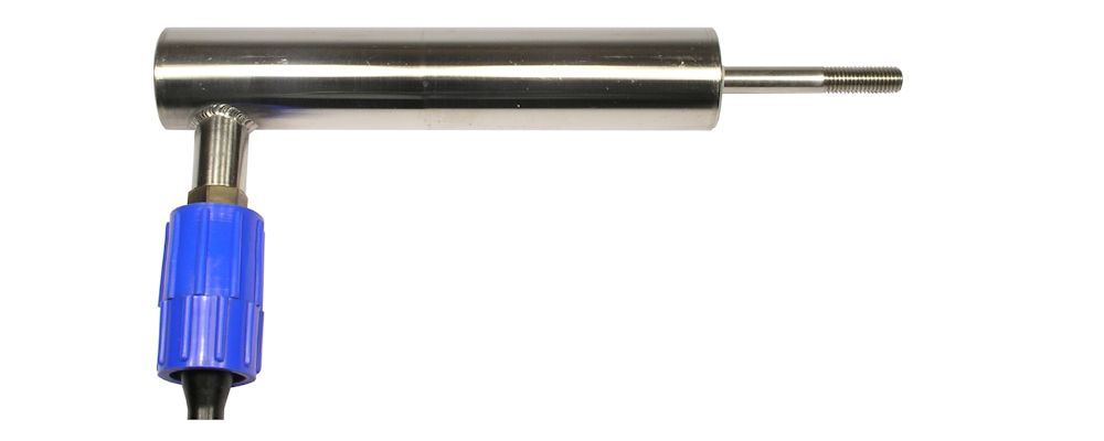
 D5W Submersible LVDT Displacement Transducer
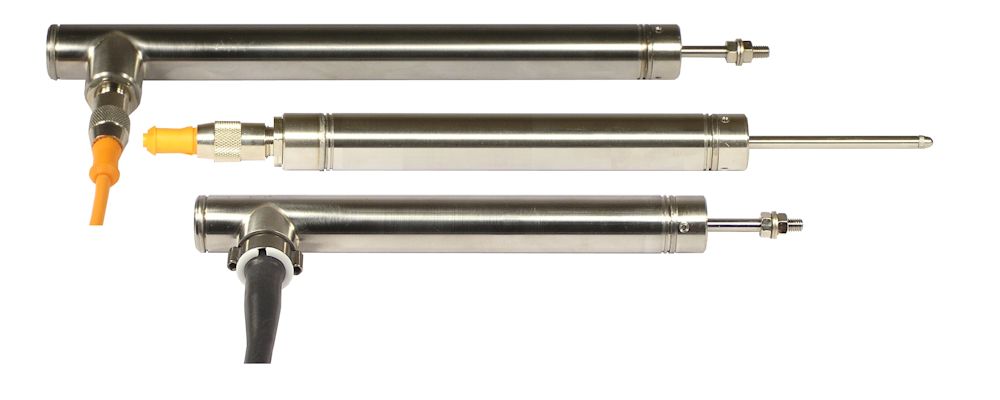 ACW Submersible LVDT Displacement Transducer
 DCW Submersible DC to DC LVDT Displacement Transducer
 SSA Seawater Submersible LVDT Displacement Transducer
 SSD Seawater Submersible LVDT Displacement Transducer
 LIN Extreme Environment Displacement Transducer
 PY Extreme Environment Non-Contact Displacement Transducer
 LDC Series Internally Amplified LVDT Displacement Transducer
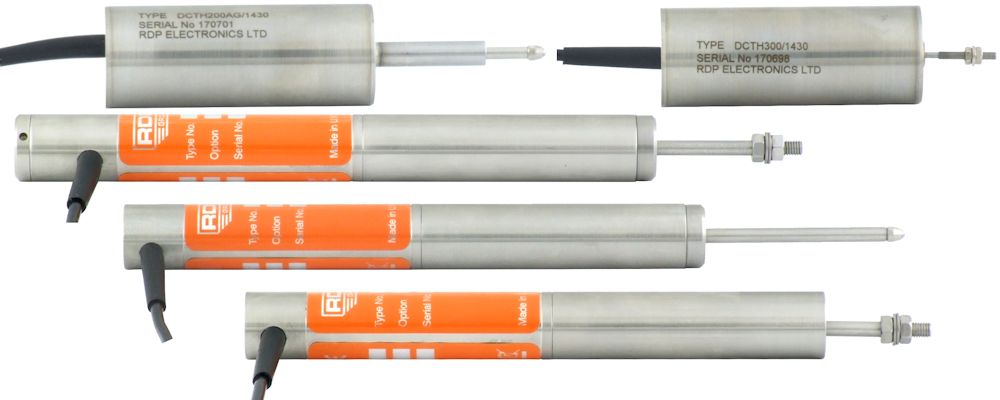
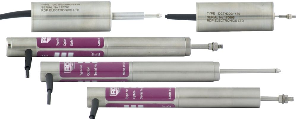
 DCTH Series Internally Amplified LVDT Displacement Transducer
How to choose the Environment for my LVDT sensor
RDP LVDT transducers are very robust and reliable but it is important to select the correct LVDT for your environment.
A clean dry environment ranges from use in a laboratory to a typical manufacturing line. Most of our LVDT transducers will tolerate being splashed with non-corrosive and non-conductive oil. RDP LVDTs are made of stainless steel so you just need to ensure that non-compatible fluids do not get inside the transducer where the electronics live. Any tacky substances that could cause the sliding parts to stick should be avoided. Particulate matter is only an issue if it causes mechanical seizure of the moving parts. Fragments of metals that are attracted by a magnet should not be allowed to enter the inner mechanics of the transducer.
A moist environment is where there is very high humidity or splashed water us such as outdoors. The transducers should ideally be mounted with the armature pointing vertically downward or at worst horizontally. Any water that collects in the inner tubes of the LVDT could be forced under pressure by the moving armature into the inner electronics and so a submersible unit would be necessary if this is a possibility.
Our waterproof and submersible sensors are suitable for long-term submersion in fluids that are non-corrosive to stainless steels and other metals used in construction. The pressure rating of the waterproof transducer depends on the electrical cable option selected.
Finally for use in seawater then our range of specific seawater submersible LVDTs is the choice; these are submersible up to 2.2km for 10 years or more.
Any LVDT transducer should be protected from ice as it could at the least cause the transducer to seize but could in extreme cases cause the transducer to me damaged. They can be used well below freezing but they must be dry.
If your environment is not described here then please contact us; we have designed LVDT sensors for use in liquid lead at 400℃ as well as LVDTs for cryogenic environments so we will almost certainly have the answer.
How to choose the Output for my LVDT sensor
An LVDT is a transformer and requires a specific type of signal conditioning amplifier of which there are many in our product range. Having the amplifier remote from the LVDT transducer means that the LVDT is not limited by the temperature constraints of the electronics.
However, it is possible with many of our LVDT sensors for us to fit the amplifier inside the transducer. This means that you can supply the unit with a dc voltage a get a dc output (or 4-20mA) and keep all of the advantages of the LVDT principle.
If you want to have a digital display with your LVDT transducer or would prefer an external amplifier so that you can make adjustments to the output then select LVDT, choose your sensor and then select from our range of accurate LVDT amplifiers and digital display modules.
Additionally our LVDT transducers will work with the majority of full bridge LVDT amplifiers so if you already have an amplifier then our LVDT output will probably be compatible (although you should check!)
How to choose the Mechanical Type for my LVDT sensor
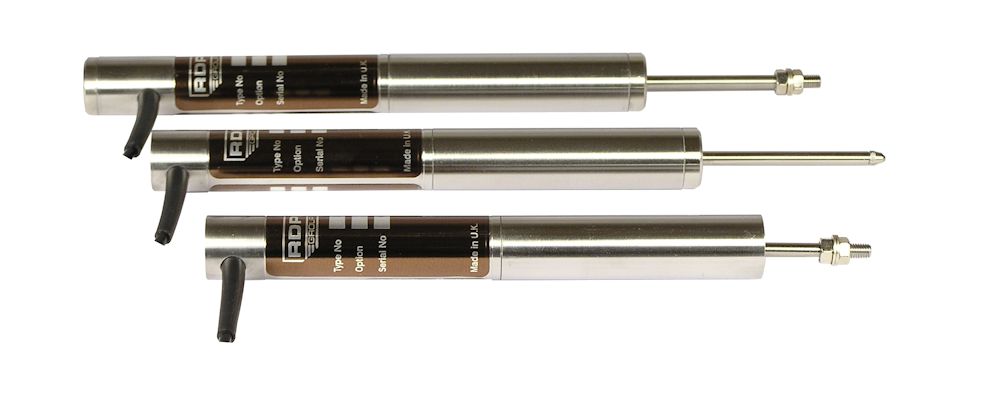
Unguided version
The armature assembly (the moving part) is a completely separate component from the body of the LVDT and when correctly installed are the most robust and reliable. These are the best types to use if you can because there is no physical contact between the armature and body but you must not touch the sides so be sure that the external guidance is good.
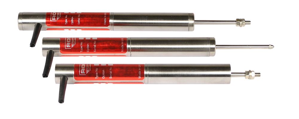
Captive guided version
The armature assembly is guided internally by bearings. In many installations the Captive Guided LVDT transducer can be used between end bearings to take out moderate misalignment.
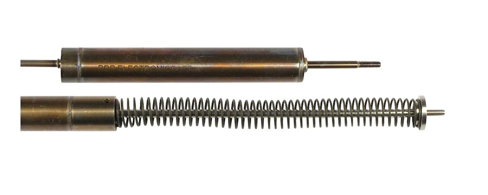
Spring return version
The armature is pushed outward by an internal spring. The Spring Return LVDT is best where the target may move far away from the LVDT (so it just loses contact) or where there is lateral movement of the target with respect to the armature.
Air push version
In an Air-Push LVDT the spring retracts the armature assembly; The armature is moved out by the application of air pressure to the air port on the LVDT. This type is used where the LVDT armature needs to be moved out of the way of components moving along a conveyor for example.
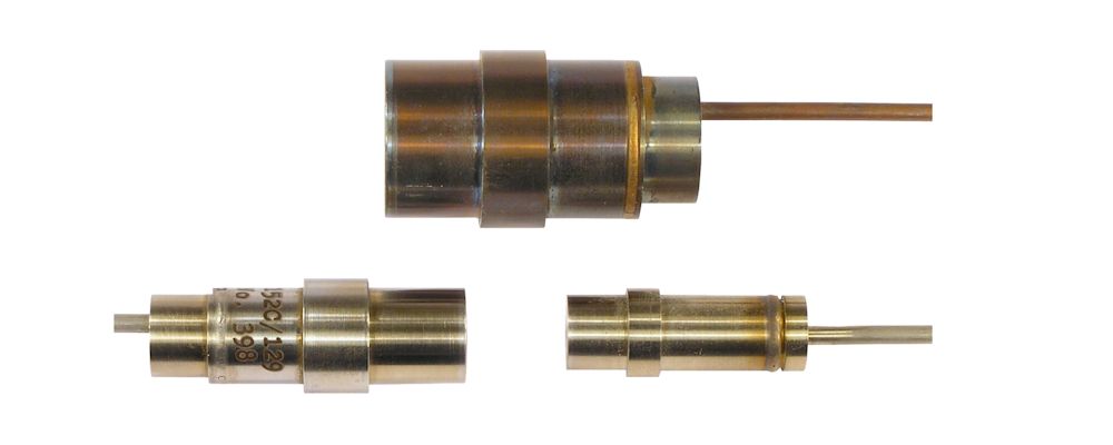
Non-contact
A non-contact transducer makes an accurate measurement of the gap between the front face of the sensor and a suitable metal target.
How to choose the measurement Range for my LVDT sensor
The range of an LVDT is the linear distance it can measure. When selecting the transducer range it is important that it is just enough for the distance you need to measure. The accuracy of an LVDT is at an optimum when it is used over its full working range.
The options in the range selection are the full working range of the LVDT. Some LVDT transducers have their range expressed as plus/minus half their working range. For example a transducer with a range ±50mm actually has a range of 100mm (from -50 to +50).
How to choose the Temperature for my LVDT sensor
The temperature selection details the upper and lower operating temperature for our range of LVDT sensors. The operating temperature range of most of our LVDTs is suitable for most industrial environments.
If you need to measure in a very hot or a very cold environment then you will probably need to consider an LVDT that does not have an internal amplifier because this reduces the operating temperature range of the sensor. We have a wide range of external amplifier that can be located away from the sensor in an environment where the temperature is suitable for electronics.
On many of our unamplified LVDTs there are options available which increase the upper operating temperature limit to 200℃. If you need hotter than this then our LIN series may be the answer
How to choose the Radiation tolerance of my LVDT sensor
The radiation selection is normally not important; our LVDT sensors are all suitable for the radiation levels of a normal industrial environment where people have unrestricted access for example.
In higher radiation environments then you should select transducers that do not have built-in amplifiers (so have an LVDT output) and locate an external amplifier away from the radiation.
We have a number of sensors that can withstand extreme levels of radiation, please contact us to discuss your requirements.
How robust is an LVDT
All RDP transducers are housed in a robust stainless steel housing which provides both mechanical protection for the LVDT sensor as well as shielding the internal coils and electronics from external electromagnetic interference. The housing also serves to contain and concentrate the magnetic fields generated by the coils inside the LVDT.
The coils themselves are precision wound with a controlled tension. Once they are tested and optimised they are coated to homogenise them into a more solid, stable unit increasing the resistance to shock and vibration.
When correctly installed unguided LVDTs have no physical contact between the body of the transducer and the moving armature and therefore there is no wear. A correctly installed unguided LVDT therefore is very robust and has a MTBF (mean time between failures) of around 200 years using the parts count method.
On our captive and spring return transducers the armature assembly is guided using low friction bearings again with very low wear and extremely long life.
Where waterproof LVDTs are needed the case and inner tube are welded together between end caps and a suitable submersible electrical termination so that the coils and the electronics are hermetically sealed between the stainless steel tubes. This is because the magnetic principle of operation means that the core only needs to be inside the transducer for the LVDT to work, it´s even OK for suitable fluids to fill the inner tubes of a submersible LVDT.
So a robust housing, solid and stable winding, very few internal connections and no electrical contact across the sensing element means that LVDTs are about the most robust and reliable displacement sensor available.
What is the resolution of an LVDT
The resolution of an unguided LVDT is infinite! We have had customers who have told us that they can detect the vibration of traffic passing in the street outside.
The limiting factor to the resolution of an LVDT is the guide bearings and the signal conditioning electronics. The bearings typically create a resolution of a couple of thousandths of a millimetre (less in the case of gauging transducers). The signal conditioning electronics will have a small ripple but this is at quite a high frequency and so of most applications it won´t even be noticed.
How accurate is an LVDT
Accuracy in the context of this definition is the sum of the errors due to Hysteresis, Repeatability and Linearity.
Hysteresis is a measure of the ability of a sensor to return to a starting value after a full scale value is applied then removed. For an unguided LVDT this is zero, there is no error due to Hysteresis.
Repeatability is a measure of the ability of a sensor to give the same output when the sensor is repeatedly retuned to the same position. For an unguided LVDT there is zero repeatability error although on spring and captive types a small (<0.003mm) error may be introduced by the bearings.
Linearity Error is a measure of the difference between a perfectly linear output and the actual output of the sensor. In a perfect sensor, a graph of the output across the full scale range of a sensor would be a straight line. The Linearity Error is a measure of the difference between this perfect output and the actual output curve of the sensor. Because we believe that it is the most representative we use the BFSL (Best Fit Straight Line) or Least Squares method of linearity calculation. For most (but not all) of our sensors the standard error is ±0.5% of full scale with options on many sensors of ±0.25% and ±0.1% of full scale. The individual product pages for our sensors detail the standard linearity error for the sensor and the options available.
Because the Linearity Error of an LVDT is very repeatable (so the errors are always the same) it is possible to use external correction of the output to give even higher accuracy.