High accuracy
High cycle life
Submersible
Stainless steel
High resolution
Voltage / 4-20mA output
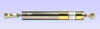
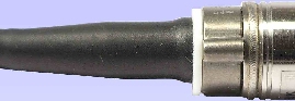
These transducers are for displacement / position measurement. They make an accurate position measurement of the movement of the armature (the sliding part) relative to the body of the displacement transducer.
This transducer uses the Linear Variable Differential Transformer (LVDT) principle which means that it is probably the most robust and reliable position sensor type available. The strength of the LVDT sensor's principle is that there is no electrical contact across the transducer position sensing element which for the user of the sensor means clean data, infinite resolution and a very long life.
Our DC to DC LVDT transducer has all of the benefits of the LVDT sensor principle with the added convenience of built-in LVDT electronics enabling a dc supply and dc output. As an option we can offer a 4-20mA 2 wire connection to the transducer on some models.
Our submersible displacement transducers are designed to make measurements whilst submerged in suitable liquids. Fluids which are non-magnetic can be allowed to flood the armature tube without affecting the operation of the transducer.
This series of displacement transducer is available as either an unguided, captive or spring return version.
Electrical supply options
| DCWH | Supply ±15V, Output ±5v |  Data sheet Data sheet |
|---|---|---|
| DCWV | Supply 24V, Output 0-10V Isolated | Data sheet |
| DCWL | Supply 6-18Vdc, Output ±2.2V Isolated | Data sheet |
| DCWC | Supply 24V, 4-20mA 2 wire | Data sheet |

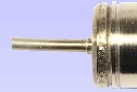
Unguided version.
On our DCW unguided LVDTs the armature assembly is a separate component, to make a measurement the user must guide the armature inside the body without touching the sides. Our DCW unguided position measurement transducers are appropriate where external guidance is available and give truly non-contact operation
DCWH100 to DCWH400
CL1=2.4''
D1=0.811'' ±0.005''
D3=0.08''
ID=0.100''
TF=M3x0.5, 0.72''
X=Center of range
DCWH500 to DCWH8000
CL1=2.4''
D1=0.811'' ±0.005''
D3=0.187''
ID=0.268''
TF=M5x0.8, 0.59''
X=Center of range

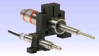
Captive guided version.
Our DCW captive guided displacement transducer has bearings to guide the armature inside the measurement sensor. Our DCW captive LVDTs are for position measurement applications where guidance may be poor and end bearings may be required.
DCWH500B to DCWH18500B
CL1=2.4''
D1=0.811'' ±0.005''
D3=0.19''
TF=M5x0.8, 0.59''
X=Center of range

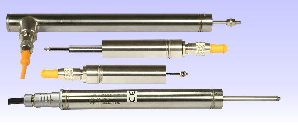
Spring return version.
Our DCW spring displacement transducer has bearings to guide the armature inside the measurement sensor and a spring which pushes the armature to the fully out position. Our DCW spring return LVDTs are appropriate where it is not possible to connect the transducer armature to the moving component being measured.
DCWH100A to DCWH400A
CL1=2.4''
D1=0.811'' ±0.005''
D2=0.31''
D3=0.16''
L2=1.40''
X=Center of range
DCWH500A to DCWH3000A
CL1=2.4''
D1=0.811'' ±0.005''
D3=0.19''
X=Center of range
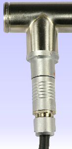
Electrical termination options
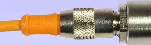

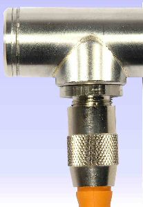
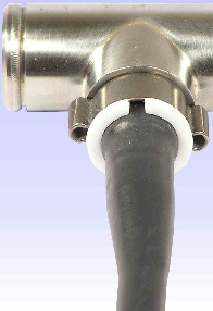
Option code 11 - Side exit part-sleeved integral cable and conduit fitting
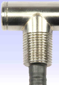
CBX = 1.0''
TR = M5x0.8, 0.43''
CL1 = 1.0''
CL2 = 2.0''
TC = 1/2''-14 NPT, 0.78''
CBD = 7.3''
CSL = 6''
Cable length = 39.4'' to 3281ft
Operating temperature range* = -40℉ to 194℉
Maximum static pressure* = 247psi
TR = M5x0.8, 0.43''
CL1 = 1.0''
CL2 = 2.0''
TC = 1/2''-14 NPT, 0.78''
CBD = 7.3''
CSL = 6''
Cable length = 39.4'' to 3281ft
Operating temperature range* = -40℉ to 194℉
Maximum static pressure* = 247psi
*Transducer and cable option specifications should be compared and the worst figures used
Specification
Specification
Specification DCWL
Specification DCWV
Options And Accessories